eBUS Adapter Shield Interface (“easi>”)
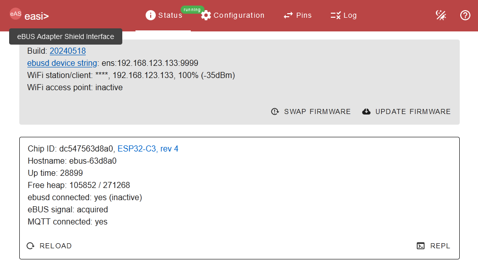
When the adapter is available in the network (via WIFI or Ethernet), it can be configured with its own web page. This also offers access to the command line interface (REPL).
If the adapter is in configuration mode (see button), the command line interface (REPL) is also available via serial (USB or Raspberry Pi).
This allows adjusting the configuration and a lot more, see below.
Web page

With the integrated web server, the adapter can be configured via WIFI as well as via Ethernet (if a W5500 module is plugged in).
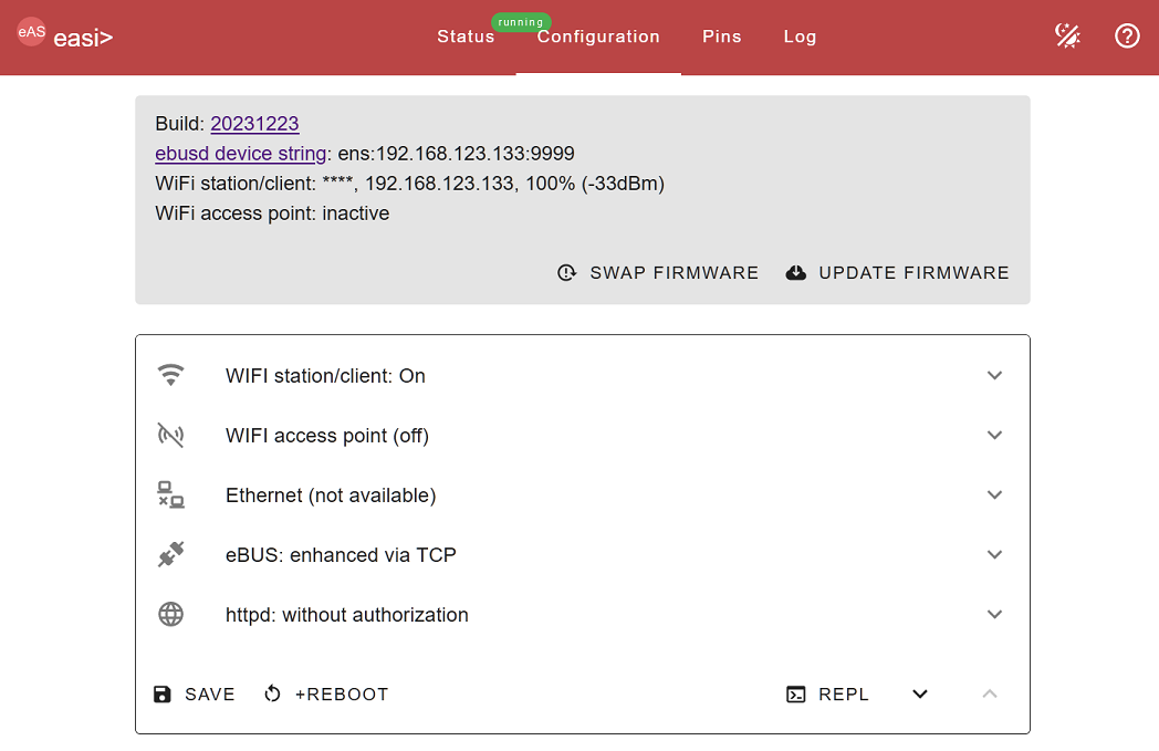
The tab “Configuration” allows adjusting all settings for WIFI station and accesss point, Ethernet (when available) and eBUS:

The association of functions with pins is done in the “Pins” tab. As soon as sensors are detected after configuration, the measurement appears in the “Status” column:

All data exchange between the web application and the web server in the adapter is in JSON, so the data and status can be queried and configuration can be changed via HTTP as well.
Command line interface (REPL)
The “easi>” command line interface (REPL=Read-Eval-Print Loop) allows using all functions of the adapter, only some of which are available in the web application. This way the network performace can be measured via iperf e.g., or access credentials to another WIFI access point can be tested.
All available functions are listed via the “help” command.
Checking the pins
For use with USR-ES1 or W5500 module for Ethernet it is important that the pins have a stable and functioning connection to the plug-in module. If this is not the case, the module cannot be recognized by the firmware.
Apart from that, we have had many USR-ES1 items that were simply broken even though the LEDs were lit.
In order to check this, a short wire is sufficient. This is done as follows:
- disconnect all connections except the power supply (also remove the Ethernet module) and plug one end of the wire into a GND pin (e.g. pin 8 on W1, i.e. the one closest to the USB socket).
- set all pins to input with the “+all in” button on the website in the “Pins” menu and save with “+APPLY”. Then all IO pins (0-6 and 8) must be shown as “H” in the “Status” column.
- as a first test, plug the other end of the wire onto the RX or TX pin, which should make the green or red LED light up.
- now plug the other end of the wire into one of the IO pins 0-6 or 8 one after the other and click on the reload button in the “Status” column. Then only the selected IO pin may show an “L” and all others must remain at “H”.
If the test is not successful for all IO pins 0-6 and 8, then the connection is not OK. This is most likely due to a loose connection or a cold solder joint. Then simply solder the corresponding pin a bit.