PIC Firmware
The PIC requires firmware in order to run and will be delivered with the current version initially.
Firmware Update / Configuration
The initially delivered PIC firmware contains a bootloader that allows updating as well as configuring the firmware via USB, WIFI, or directly via Raspberry Pi GPIO/ttyAMA0.
This is done best with the ebus PIC Loader tool which also allows setting a fixed IP address (for the Ethernet variant), the arbitration delay, and further parameters.
To update or configure the firmware, the adapter has to be configured to USB, WIFI, or Raspberry Pi variant, i.e. the USR-ES1 module (in the Ethernet variant) has to be removed.
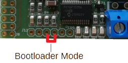
To then activate the bootloader, pins 3 and 4 on J11 have to be bridged (e.g. using tweezers or a short wire).
Since version 20221105 it is sufficient to hold that bridge shortly until the PIC has rebooted.
Before version 20221105 a reset has to be issued simultaneously (with the bridge in place) by either using J12 (see Reset below) or connecting the power supply.
Afterwards the bridge can be removed again.
When the bootloader is active, the blue LED lights up immediately very brightly (more than all others see here).
In order to update the firmware, the
ebus PIC Loader
is used like this, where /dev/ttyUSB0 may have to be replaced by the actual USB serial device or the address as stated by ebusd-esp PIC-passthrough (when using WIFI):
ebuspicloader -f firmware.hex /dev/ttyUSB0
Firmware Versions
Current Version 20221231:
- Firmware version as reported by ebus PIC Loader:
1 [8419] - Features:
- ebusd enhanced protocol V1 including high-speed mode
- Ethernet with DHCP or fix IP
- extra infos
- configurable arbitration delay
- support for v3.0 and v3.1
- variant adjustment via ebus PIC Loader
(only via jumper at J12 before version 20221206)
- Changes: see Changelog
- Minimal ebusd version:
- Pins at J12: see variant adjustment
Former versions: see Changelog
Variant adjustment
Since version 20221206 the variant can be adjusted via ebus PIC Loader and the jumpers at J12 are obsolete (no longer soldered in as well).
The following variants are possible:
- enhanced USB/RPI (high-speed)
- enhanced WIFI
- enhanced Ethernet
- non-enhanced USB/RPI/WIFI
- non-enhanced Ethernet
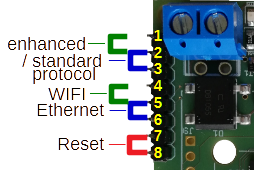
Pins at J12 (only relevant for firmware versions before 20221206)
- Pin 1: Vdd
- Pin 2: ebusd protocol:
- open (or connected to pin 1): ebusd enhanced protocol (high-speed with v3.1, depending on pin 7 with v3.0)
- to GND (pin 3): standard protocol (eBUS direct)
- Pin 3: GND
- Pin 4: WIFI
- Pin 5: Variant:
- open: RPi or USB
- to WIFI (Pin 4): WIFI
- to GND (Pin 6): Ethernet
- Pin 6: GND
- Pin 7:
- open: normal-speed serial (only for v3.0 with enhanced protocol, since version 20220731)
- to GND (Pin 6): high-speed serial (only for v3.0 with enhanced protocol, since version 20220731)
- Pin 8: Reset: shortly to LOW (Pin 7) or GND
Important note: The pins at J12 must never be connected to any pin on the other jumpers/pin headers/sockets as separate power sources are used here. Any connection endangers the adapter and devices on the eBUS!
Ethernet Configuration
In case a fixed IP address is supposed to be used with the USR-ES1 module instead of obtaining it via DHCP, this can be done with the ebus PIC Loader. For this, the bootloader needs to be activated first, see above.
For example, to set the IP address 192.168.10.20 with a network mask of 255.255.255.0 (=length 24), the ebus PIC
Loader is called as follows:
ebuspicloader -i 192.168.10.20 -m 24 /dev/ttyUSB0
LED
The blue LED is used to signal states from the PIC firmware. In general, the bootloader and normal modes are quite different.
LED in bootloader mode
If the LED lights up permanently very brightly (more than all others) immediately after supplying power, the PIC is in bootloader mode and is waiting for commands on the serial interface.
LED in normal operation (without Ethernet)
In normal operation, the blue LED is initially turned off after supplying power.
- If the LED is on after a short period of time with very low brightness, the enhanced ebusd protocol is deactivated
(see jumpers). - Otherwise, it is fading up to normal brightness.
- After each initialization in the enhanced protocol, it lights up very brightly (more than all others) for 2 seconds.
- As sign-of-life it pings every 4 seconds
- In case of a protocol error on eBUS or host, it lights up very brightly (more than all others) for 5 seconds.
LED in Ethernet operation
If the USR-ES1 Ethernet module is plugged in and the variant set to Ethernet, the blue LED shows further state information in addition to those described above, and these are stepped through in the following stages:
- Until the W5500 of the USR-ES1 module responds after the reset, the LED flashes (2x per second).
- Until a link is found on the line, the LED flashes very quickly (20x per second).
- In case of DHCP, the LED flashes quickly (4x per second) until an IP address has been negotiated via DHCP.

