Start using the adapter
First steps
After delivery, a few steps are necessary to put the adapter into operation:
- Flash adapter
- Configure adapter
- Install ebusd
- Configure ebusd
- Connect eBUS
- Receive / send eBUS messages
Delivery
There are slightly different versions of the adapter, which is reflected in the following aspects:
-
eBUS connector: this is already plugged in and is either green or black.
-
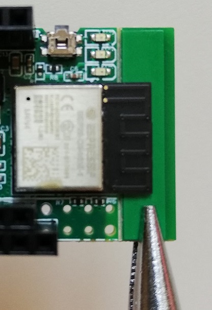
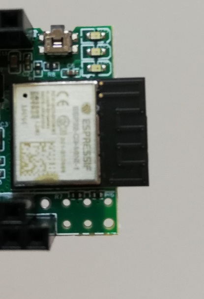
PCB: this can have a 7mm extension under the ESP antenna. The extension is from production and is kept for safer transport. Should it get in the way, it can simply be broken away downwards e.g. with a pincers.
Attention: When using the adapter via WIFI, it is better to remove this extension as it might have a GND layer, shielding the antenna unnecessarily.with extension: without extension: 

-
middle LED: this is either green only or yellow-green.
Except for the extension (for WIFI only), these aspects have no influence on the operation of the adapter.
Flash adapter
The adapter is already delivered with flashed firmware, as this is necessary for testing before delivery. However, the version may already be outdated and it is recommended to bring it up to date.
Newer firmware versions can be easily updated via OTA directly on the adapter website.
The firmware can always be flashed and also updated by using a web browser supporting Web Serial .
Just follow the steps on the firmware page.
After that, the easi> interface is already available directly for configuration in the flasher via “LOGS & CONSOLE”.
At the same time, a still unconfigured firmware starts a WIFI access point with SSID “EBUS” without a password. When connecting with that one, the most important settings can be adjusted on the web page http://192.168.4.1. As long as the adapter has not yet been configured, WPS with push button mode (PBC) is also activated.
Configure adapter
The easiest way of configuration is via WIFI. This can be done via the access point (SSID “EBUS” without a password), that is started after initial flashing (and afterwards when pressing+holding the button during boot), as well as after configuring the access data for your own WIFI via the flasher in the firmware page as noted above.
Alternatively, the easi> interface can be used via serial connection as well. This is possible directly through the firmware page as explained above, or via putty, minicom or any other terminal software allowing to connect to the serial USB port. Then the easi> interface of the adapter appears that offers many commands for configuration and testing. Using the “help” command reveals them including the parameters.
When using Ethernet, it is recommended to use the steps described above for initial setup, as the Ethernet interface needs to be configured first.
Install ebusd
If communication is to be taken over by ebusd, it needs to run somewhere.
This can be
- directly on a Linux host by installing a Debian package of the last release or by compiling the sources,
- or as Docker container including being run as Home Assistant Addon via Supervisor.
Configure ebusd
Depending on the host connection, the ebusd device string has to be adjusted. In addition, the enhanced mode is not yet set in the device string of a freshly installed ebusd. How this device string must look exactly can be found in the details of the host connection.
With the Docker container, this is passed as an argument to ebusd in the compose file or in the docker run line and
in case of an installation entered under /etc/default/ebusd. The following settings are available there by default:
EBUSD_OPTS="--scanconfig"
Without further information, ebusd uses /dev/ttyUSB0 as the device. Because of the enhanced mode and if the adapter
is not connected via USB, the device string has to be set. For USB it would look like this:
EBUSD_OPTS="--scanconfig -d ens:/dev/ttyACM0"
And for WIFI or Ethernet it could e.g. look like this:
EBUSD_OPTS="--scanconfig -d ens:192.168.0.50:9999"
If ebusd is started now, the following lines should appear in the log file (/var/log/ebusd.log or Docker Logging,
values in brackets depend on the respective configuration):
<DATE TIME> [main notice] ebusd <VERSION>> started with auto scan on enhanced device <DEVICE>
...
<DATE TIME> [bus notice] device status: resetting
...
<DATE TIME> [bus notice] device status: reset, supports info
Connect eBUS
Now the eBUS line can be connected to the adapter. The polarity does not need to be taken into account. Messages from other participants on the bus should then appear in the logging, for example as follows:
<DATE TIME> [update notice] received unknown MS cmd: 1050b505072b000100000000 / 00
...
<DATE TIME> [update notice] received read ehp Status QQ=10: 18.94;1.540;2.340;off;00
Receive / send eBUS messages
Before you take care of further integrations, the communication
via ebusctl should be checked first. The best way to do this is to see which messages are available through the
automatic scan process with ebusctl find.
The output list contains the message ID (circuit followed by name) and, after an equal sign, the data last received
(within the last 5 minutes). For example, if the following entry is part of the list:
hwc Mode = no data stored
then this can be actively read out with the command ebusctl read -c hwc Mode, which might yield in the following result:
hwc Mode = 53;auto;disabled;hwc;00;day
Checklist
In order to not forget anything, here is a checklist of the above:
- update adapter if necessary and configure it, easiest way:
- update and connect to WIFI via browser with web serial via firmware page
- set desired host connection via the adapter’s website (only necessary for USB/Raspi, default is TCP)
- watch the details for Raspi-GPIO connection
- install ebusd and configure it:
- device string
ens:<ip>:9999(TCP) /ens:/dev/ttyACM0(USB) /ens:/dev/ttyAMA0(Raspi) depending on the connection - for WIFI maybe add “–latency=30” depending on the traffic in your own network
- device string
- connect eBUS with 2-wire cable e.g. bell wire (the polarity does not matter)
- receive messages, get started with integration